| University | National University of Singapore (NUS) |
| Subject | Mechanical Engineering |
Kinematic and Dynamic Analysis of Linkage Mechanisms
The six-bar linkage mechanism shown below:
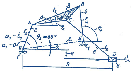
Given data:
| l2 = OA | = | (m) |
| θ1 | = | |
| θ2 | = | 60° |
| β | = | |
| n2 | = | rpm |
Determine:
| l1 | = OE | = | (m) |
| l3 | = AB | = | (m) |
| l4 | = BE | = | (m) |
| l5 | = CD | = | (m) |
| AC | = | (m) | |
| H | = | (m) | |
| θ3 | = | ||
| θ4 | = | ||
| θ5 | = | ||
Guidelines for choosing the remaining dimensions of the mechanism:
Stuck with a lot of homework assignments and feeling stressed ? Take professional academic assistance & Get 100% Plagiarism free papers
Following questions:
- Determine all possible positions of links and joints by graphical position analysis. Draw to scale all positions of joints for sixteen subsequent positions of link 2 and determine the limits of motion where appropriate. Identify and outline the paths of each moving joint.
- Determine linear and angular velocities by graphical velocity analysis for the given position 2 = 60 of the mechanism, as shown above. Draw to scale the velocity vector diagram encompassing all linear velocities to scale and present the results in a tabular form.
- Determine all linear and angular accelerations by graphical acceleration analysis for the given position 2 = 60 of the mechanism. Draw to scale the acceleration vector diagram encompassing all linear accelerations to scale and present the results in tabular form.
- Determine all instantaneous centers of velocity for the given mechanism using Kennedy’s rule, and velocities of joints A, B, C, and D using identified instantaneous centers. Draw all instantaneous centers and velocities to scale on a separate diagram of the mechanism.
- Obtain analytic solutions for positions, velocities, and accelerations by vector loop equations and complex number notation and present the results in a tabular form. Compare these results with those obtained using the graphical approach. You should have a good correlation.
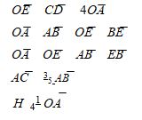
- Determine all dynamic forces at the joints for the given position of the mechanism using the analytical matrix method. Assume, for link 2: m2 = 1 kg, CG at OA/2, I2 = 0.002 kgm2; for link 3: m3 = 2.5 kg, CG at /2 and AB/2, I3 = 008 kgm2; for link 4: m4 = 1.5 kg, CG at EB/2, I4 = 0.005 kgm2; for link 5: m5= 1.8 kg, CG at CD/2, I5 = 0.006 kgm2; for slider 6: m6 = 0.9 kg and CG at D.
- Determine the shaking force and moment, and work out analytically an optimal strategy for balancing the given mechanism. Discuss the results.
- Develop an equivalent computer model capable of simulating the motion of the given mechanism using the software Working Model and compute and plot the paths, velocities, and accelerations over one revolution of the crank at the given angular velocity. Also, find the pin forces, slider side loads, and driving torque over one revolution. How do the results compare with those obtained using the graphical and analytical approaches?
Get Help By Expert
Singapore Assignment Help provides remarkable engineering assignment help services to all levels of engineering students. We have a huge number of assignment writing experts to provide mechanical engineering assignments and homework help to all students.
Answer

Looking for Plagiarism free Answers for your college/ university Assignments.
Recent Solved Questions
- CVEN3501 Water Resources Engineering Coursework Brief 2026 | UNSW
- MKTG101 Marketing Coursework Brief 2026 | Singapore Management University
- NCO102 Effective Writing Tutor-Marked Assignment 1, 2026 | SUSS
- SC1101E Making Sense of Society Written Assignment 1 Brief 2026 | NUS
- BUSM2653 People Analytics Assesment 1 Insightful Analytics Report 2026 | SIM
- MLA604 Maritime Operations Assessment Brief 2026 | MLA College
- ICT226 Enterprise Systems and Integrated Business Process End-of-Course Assessment 2026 |
- OMGT2229 Strategic Supply Chain Assignment 3, 2026 | RMIT University
- NCO103 Listen and Be Heard: Effective Communication through Storytelling TMA 02, 2026 | SUSS
- PSY259 Personality and Individual Differences End-of-Course Assessment 2026 | SUSS