PSB5048EE Assignment Brief
CW 1: Design an embedded Smart Safe Device (SSD)
Learning Outcomes
1. Work as part of a team to identify, review and select techniques, procedures, and methods to undertake embedded development taking into consideration client requirements, costs of development/commercial risk / health & safety, environmental/recycle.
2. Develop test and implement an embedded system
3. Present outcomes to a client and a wider audience.
Task
The tasks are chosen to enable you to get experience in the design, implementation, and testing of real-time embedded systems.
Design, implement and test a solution to the following problem:
You will be using a PIC18F4550 microcontroller board to design and produce a versatile prototype.
The following tasks must be completed by the team:
Design and build a prorotype that performs the following tasks:
1. The functional system implementation is based around the PIC18F4550 microcontroller. The standalone unit is remotely controlled via an Asynchronous Serial Interface by a host device.
2. The remote-control aspect of the communication is via a wireless Bluetooth communication device mounted on the remote lock system while the controlling device could be a smart phone, a Tablet, or a remote PC. The remote device sends a three-digit user selected code that locks and unlocks the system.
3. On receiving a correct 3-digit numeric PIN the locking or unlocking function can be selected.
A ‘menu’ to be created on the remote device to display the various options:
a. A welcome message and with a friendly and helpful instruction to guide the user how to use the app. Student can use existing apps available from the store (no bonus points). Or student can choose to write their own smartphone app, or PC app (bonus points to be awarded separately).
b. Lock function, is to lock the locking mechanism using a relay board
c. Unlock function is to unlock the locking mechanism using a relay board
d. Change password function
e. Enable or disable encryption function (bonus points to be awarded separately)
4. The secure code is set by the user (owner). The code should be stored in the non-volatile area of the PIC’s EEPROM.
5. The user would only be given the chance for three retry entries. An unsuccessful lock/unlock sequence will initiate an alarm condition on the remote lock unit via an on-board buzzer and by a flashing an RGB LED. The system should remain inactive for a specified time interval (e.g. 5 sec to 10 sec).
6. The RGB LED and buzzer will also be used for feedback purposes during the selection of the various system operational functions.
7. The locking/unlocking mechanism of the system is implemented via a solenoid with the appropriate driver interface.
8. The student is to design a complete hardware circuit and should include the various blocks:
a. The solenoid and its relay module
b. The RGB LEDs
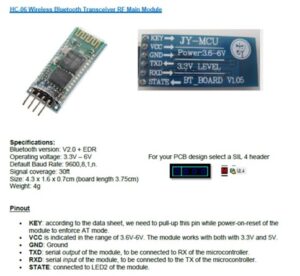
c. The Bluetooth module with UART interface
d. 1 buzzer
e. 1 numeric 3×4 (preferred) or 4×4 Keypad interface to the MCU (PIC18F) for local pin entry
Note: The pin entry via keypad and the BT app must work together in one main program. The entry is either done via keypad or BT app to complete an operation.
The development kit will be represented as a module in the completed hardware design and do not need to design the detailed PIC18F4550 MCU circuit. Connector provisions should be made for connecting your circuit to the development kit module.
A schematic must be captured, showing clear details of all parts of the schematic and to be included in your report.
9. A double layer PCB of your design should be included in your report showing the PCB layer(s) and the 3D view. The size of your PCB design should not exceed 15 cm x 15 cm. All selected PCB component can be either Through Hole or Surface Mount Technology type. Your PCB should be a 0.8 mm FR4 laminate, 1 ounce copper. The pcb (including the 3D view) must be captured in your report.
10. A full listing of the Bill-Of-Materials (BOM) of your designed product should be included in your report with full references to component supplier’s order codes and prices. All components chosen should be ROHS approved. An overall cost of your design should be given including your PCB manufacturing quote(s). Your BOM should NOT include Development tools (such as PICKIT3, PIC18F development board and software tools).
11. A short functional demo of less than 2-3min of your protoype should be made available and submit into the blackboard. A staff signed note that shows the team’s name and team member names should be shown in your video clip.
12. Only one team report should be submitted by one team member and should include team members names. This should be a PDF file. (Please make sure that the conversion from Word to PDF follows the correct formatting).
The assignment report’s file name should begin with the team’s name and the up-loader’s surname. The other team members should upload a cover sheet with the filename: coversheet followed by the team’s name. The cover sheet template is provided on Blackboard.
Team Mark
1. This will set the scene for the report, providing information on how you planned your work and what objectives you were attempting to meet. A Gantt chart should be included in your report showing your planned activities against time. You should also include a Project Management and Risk Assessment discussion. Identify any health and safety in carrying out the practical aspect of the work as well as any environmental issues that need to be addressed.
2. The Main Body of the report will comprise the following sections:
a. Design & Implementation [15 marks]: Hardware and Firmware document the design process in writing. Implement the design running on the PIC microprocessor in the lab. All relevant input/output interfaces need to be implemented. Your code must be uploaded to the module web and all implementation decisions need to be described. The use of digital photographs and screenshots of the hardware/software set-up is permitted as part of your explanation of the implementation.
b. Component selection / Cost analysis [Hardware 5 marks]: used and provide a cost analysis. Identify component suppliers and provide the corresponding stock number order codes. Create a Bill-Of-Materials (BOM) list. Make sure that your components are ROHS compliant. Consider the environmental implications and health and safety issues that some of your design components might have.
c. Software Flowchart [Firmware 5 marks]. Firmware to develop an integration level flowchart to facilitate and help in the development of the overall firmware program.
d. Prototype & Modular Testing [Hardware 20 marks, Firmware 20 marks]: A prototype must be built and it must be able to demonstrate the intended application. Document the prototype build in your report. Independent verification of hardware and firmware/simulation to ensure that it is working before the actual integrated testing.
e. Integrated Testing / Validation [25 marks]. Document the test methodology that you have followed for your design. This must describe what tests you decided to do and why you decided to make them. You also need to document calibration procedures, debugging issues and corresponding test results.
f. Teamwork [10 marks]
Emphasis is also given to evaluate the cohesiveness of the team, and able to demonstrate the ability to work together and able to discuss issues together to resolve project issues. g. Poster and Q&A [10 marks]
The team must provide a one-page A0 poster for presentation (no print needed). Marks will be given on the details, clarity, sufficient information, presentation, and Q&A.
h. Video Recording [5 marks]
A video recording must be uploaded into the blackboard. An overall prototype demonstration (integrated features) recording is sufficient. Otherwise, for those features missing on the integrated prototype video, the relevant modular/feature testing video should be provided.
3. In your conclusions, you should survey the team’s work and results and show how the task requirements were met. You should also survey the work, describing what went well and what did not. Go back and re-asses your original planning ideas. Discuss your findings. Document the issues encountered and how you solve them. Highlight any issue that is not resolved for future work. Suggest future improvement to your design.
[Team report total 80 marks]
Individual Marks [10 marks]
Your individual Electronic Portfolio (eLogbook), cannot be the same for each team member, document the journey of your learning, the knowledge learnt, the design consideration you had went through, with detail calculation or explanations, the decision make on your design, will be uploaded to Blackboard through the link that will be provided. All laboratory activities should be discussed; solutions to tasks and fully commented software listings should also be included. All students should individually upload their personal
Portfolio. The eLogbook could be a scanned copy of your hardcopy log book that shows all your work done.
In-class Poster Presentation & Q&A Session [10 marks]. Two (or more) assessors will evaluate your individual contribution to the work to check that it meets the objectives. This will be your team’s presentation of your assignment. Each team member will be individually assessed. Questions will be asked during the session.
The team report needs to be uploaded through Blackboard via the link that will be provided. Only One Report per team to be uploaded by one team member. The other team members should upload a cover sheet that will be available via Blackboard. Your uploaded project report naming should include your team name on its title.
Your lab teams will be as defined at the start of the assignment session and cannot be changed. Teams are expected to work in pre-allocated bench areas.
You need to attend these classes promptly and follow laboratory health and safety rules.
Classes will be supervised by a lecturer/tutor.
Keep a safe copy of all coursework submitted for reference.
Key Components Used in this project:
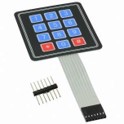
3×4 Membrane Keypad |
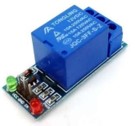
Relay Board Module |
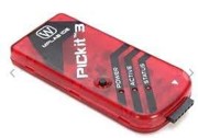
PICKIT 3 adapter |
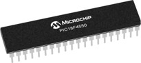
PIC18F4550 (5V version) |
 |
|
Digikey Singapore: https://www.digikey.sg/
Mouser Singapore: https://www.mouser.sg/
Element14 Singapore: https://sg.element14.com/
RS Singapore: https://sg.rs-online.com/web/
Please observe correct component handling and appropriate supply connections.
Please Do Not pull component and connecting leads by the connecting wires as this causes breakages, only use the solid part of the connector to remove these devices.
Please consult the appropriate datasheets for connection info and component parameters.
Note: it is very important that the work submitted is an individual effort. The penalties for plagiarism are severe.
The Faculty Policy on Assessed Coursework applies to this coursework. You are advised to read the guidelines available on the general Faculty CU online web site.
Keep a safe copy of all coursework submitted for reference.