| University | National University of Singapore (NUS) |
| Subject | AE604: Advanced Electronics (AE) |
Coursework cover sheet – be sure to keep a copy of all work submitted Submit online via Moodle
Submit through Moodle as a pdf document naming the file name with your student identification number (eg 15653705.pdf).
Section A – To be completed by the student – PLEASE PRINT CLEARLY
| Family Name(s) | Module No.
AE604 |
||
| Forename(s) | |||
| ID Number(s) (from your student card) | |||
| Time taken (hrs) (per student for group coursework) | |||
| Lecturer
Dam |
Submit Online Assignment by:
Week 11 of Term Refers to the blackboard for final due date/time |
||
| Module Code and Title
Advanced Electronics (AE) |
|||
| Assignment No. / Title
FM Radio Transmission Design |
|||
| Estimated Time (hrs)
20 |
Assignment type:
Individual |
% of Module Mark
25 |
Hand out date:
Week 9 of Term |
| No late work accepted. Extensions allowed only in extenuating circumstances. It is important that the work submitted is an individual effort. The penalties for plagiarism are severe. | |||
Section B – To be completed by the assessor
| Intended Learning Outcomes assessed by this work.
Design, analysis and calculation of filter design, RF power amplifier, matching network (IMN & OMN) using smith chart, antenna matching, power calculation, Free space path loss (FSPL) estimates from Transmitter system to receiver device, layout considerations, practical components selection and complete circuit design. |
|||
| Marks breakdown / Marking Scheme | Max | Awarded | |
| Overall transmitter system – explanation | 5% | ||
| Bandpass filter(BPF)design | 15% | ||
| Input matching network(IMN) design using smith chart | 15% | ||
| RF power amplifier design | 15% | ||
| Output matching network(OMN) design using smith chart | 10% | ||
| Antenna matching transformer | 10% | ||
| Power calculation from output of mixer to transmit antenna chain | 10% | ||
| FSPL to the receiver input calculation | 10% | ||
| Final complete circuit design with all values specified from output of the up-converter mixer to the antenna | 5% | ||
| Final Presentation | 5% | ||
| Note: Answer all questions. This is an individual assignment.
No copying is allowed. Student found to plagiarize may be referred to the school for action and zero marks will be awarded for both students. |
|||
| Assessor’s signature / initials: | Date: | Total 100 | Total |
| Signed internal moderator: | This work may have been moderated. You may find additional comments in the work. |
| This section may be used for feedback or other information | |
Hire a Professional Essay & Assignment Writer for completing your Academic Assessments
Native Singapore Writers Team
- 100% Plagiarism-Free Essay
- Highest Satisfaction Rate
- Free Revision
- On-Time Delivery
Coursework Task Sheet
FM Radio Transmission System
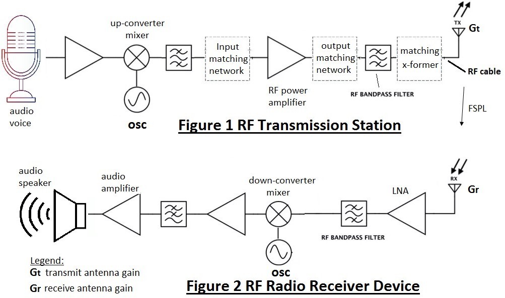
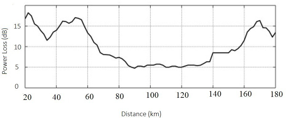
Figure 3 Power loss due to the moving vehicle, building blockage plot
Figure 1 shows a typical RF radio transmission station and Figure 2 shows a typical RF Radio Receiver Device. While Figure 3 shows the amount of additional loss to be considered in the path loss calculation due to the moving vehicle and building blockage at different location within the broadcast range. In Figure 3, a positive number refers to a power gain, while a negative number refers to a power loss.
The transmission station, as shown in Figure 1, up-convert audio frequency into a much higher frequency for long distance broadcast of up to 100km [2]. It has one-stage up-converter mixer with a local oscillator, two bandpass filter, two RF matching network and one matching transformer terminated with the RF transmission antenna.
The receiver device, as shown in Figure 2, down-convert RF frequency to audio frequency. It has a low-noise-amplifier (LNA), one bandpass filter(BPF), one lowpass filter(LPF), one down-converter mixer with local oscillator, a pre-amplifier and an audio amplifier.
The transmit antenna has a gain, Gt, of -0.75dBi to +0.75dBi [5] and the receive antenna has a gain, Gr, of -1.50dBi to 1.50dBi [5].
Consideration for building, movable vehicle blocking or cause the additional attenuation/loss to be included as per Figure 3 to be taken into account for the FSPL calculation. Student is to determine whether the received signal strength is sufficient and if it is not sufficient what should be done.
The receiver sensitivity of the receive section to ensure the circuit to function well requires a minimum of -90dBm to -60dBm [6] while the transmitter have a maximum transmit power of 0dBm to +40dBm [7].
Each student is assigned to use different FM radio frequency channels from 88MHz to 108MHz [1] and a different distance between the transmitter and receiver. The design, analysis, explanation and calculation to include the following:
a. Overall transmitter system explanation
b. Bandpass filter (BPF) design
c. Input matching network (IMN) design using smith chart
d. RF power amplifier design
e. Output matching network (OMN) design using smith chart
f. Antenna – matching quarter wavelength transformer
g. Power calculation from output of mixer to transmit antenna chain
h. FSPL to the receiver input calculation
i. Final complete circuit design with components values specified from output of the up-converter mixer to the transmit antenna.
j. Final presentation
Suggest a practical approach of the implementation. Consideration of using real world practical components for implementation is needed. RF amplifier chosen need to have the S-parameter given in the datasheet.
Also take into considerations the stray capacitance and stray inductance present in physical layout of the PCB traces and component placement.
Students could also discuss about the various signal fading experienced by FM radio broadcast including passing object such as car, building blockage, etc.
State any assumption used clearly and explain why such assumption is used.
The following tables will be given to the students:
[1] Assigned frequency table
[2] Assigned broadcast distance table for FSPL calculation
[3] Assigned additional power loss/gain chart (Figure 3)
[4] S-parameter table @ specific Vce/Ice
[5] Transmit antenna gain (Gt) and Receive antenna gain(Gr)
[6] Receiver Sensitivity
[7] Transmit power
Submit the report on due date. Wholesale copy of text & graphics from generative AI and from internet sources constitute plagiarism and student will be awarded zero marks.
Note: it is very important that the work submitted is an individual effort. The penalties for plagiarism are severe.
Keep a safe copy of all coursework submitted for reference.
Note => Please leave first page blank.
Buy Custom Answer of This Assessment & Raise Your Grades
Many students find AE604 advanced electronics assignments challenging because they need accurate RF calculations, smith chart designs, and FSPL analysis. If you are struggling with tasks like RF power amplifier design, antenna matching, or bandpass filter calculations, expert help can save you time and stress. Our writers at Singapore Assignment Help provide power electronincs assignment help that is plagiarism-free, AI-free, and tailored to Singapore university standards. get our best assignment help service today and get high grades in your assignment.

Looking for Plagiarism free Answers for your college/ university Assignments.
- MNGT3012 Business Strategy Assignment Brief 2026 | The University of Newcastle
- MGT577 AI Concepts and Applications for Business Leaders End-of-Course Assessment 2026
- MGT564 Managing Digital Transformation in Operations End-of-Course Assessment 2026
- Organic Chemistry Homework Question 2026 | Nanyang Technological University
- BUS105 Statistics Assignment Tutor-Marked Assignment Questions 2026 | SUSS
- MKTG3000 Strategic Marketing Management Assessment Brief 2026 | UON
- AVET204 Animal Nutrition, Care & Behaviour Assignment Brief 2026 | TP
- NUR3506 Translation of Evidence into Practice Assessment 3, 2026 | NUS
- NUR3507 Clinical Practice Development Project Assignment Brief 2026 | NUS
- EGE202 Application Programming Assessment Project 2 2026 | Nanyang Polytechnic